
This FPGA board needed its power controller replaced. The part is a Texas Instruments UCD9248, and it isn’t a small job: an 80-pin quad flat pack with leads on all four sides, sitting close to plastic pin headers that would melt long before the solder under the chip did.

What the UCD9248 does
An FPGA doesn’t run off one voltage. It needs a core rail, I/O rails, auxiliary rails, and often more for transceivers and memory, and most of them have to come up in a specific order. The UCD9248 is the chip that manages that. It’s a digital PWM controller for synchronous buck converters, able to run up to four output rails from up to eight phases. It sets each rail’s voltage, closes the control loop digitally, sequences the rails on and off, and watches voltage, current and temperature so it can shut things down on a fault. It talks to the rest of the system over PMBus.
That makes it a single point of failure for the whole board. If the controller isn’t doing its job, the FPGA never gets clean, correctly sequenced power, and nothing else on the board matters.
The package: TQFP-80 at 0.5 mm pitch
The UCD9248 comes in one package, TI’s 80-pin TQFP (PFC). The body is 12 × 12 mm, about 14 × 14 mm across the leads, with 20 gull-wing leads per side on a 0.5 mm pitch. Leads that fine bridge easily, and they bend if the chip is pried at before every joint is liquid. The way to lift it cleanly is to bring all 80 joints to melting at the same time and lift the chip straight up.
Protecting the headers and nearby passives
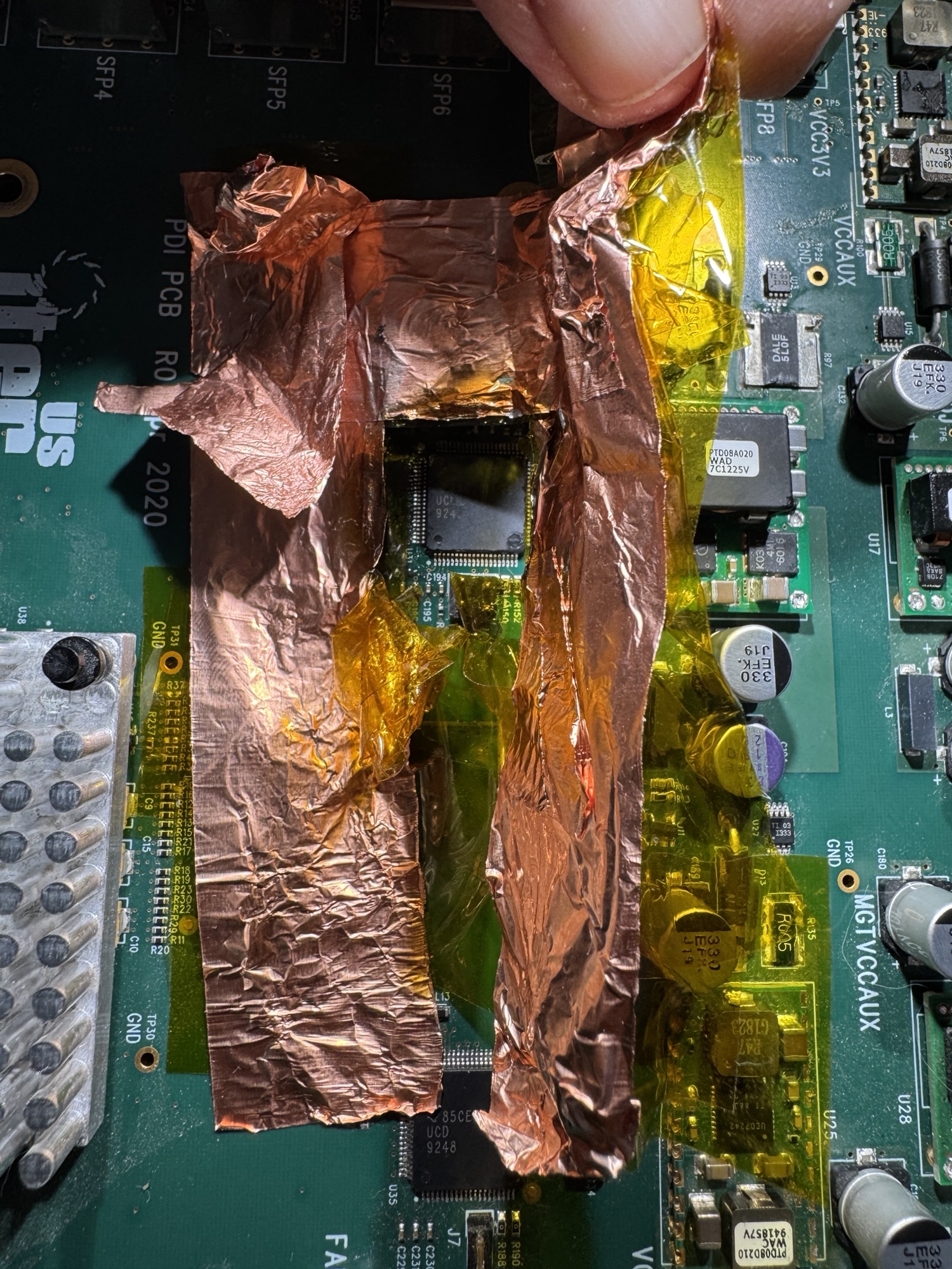
Hot air doesn’t stop at the edge of the chip. The airflow spreads across the board, and the plastic headers right next to this controller would soften and warp well below the temperature it takes to reflow the chip. So before any heat went on, I covered the surrounding area in Kapton tape and copper foil tape.
The two do different jobs. Kapton is a polyimide film that holds up to soldering temperatures without melting or leaving residue, so it keeps hot air off whatever it covers. Copper foil adds a reflective, conductive layer on top that bounces radiant heat away and spreads what it absorbs over a wider area instead of letting it concentrate in the plastic underneath.
The headers aren’t the only thing that shielding protects. The board around the chip is covered in tiny passives, 0603, 0805, 0402 and 0201 resistors and capacitors. Their joints melt at the same temperature as the chip’s, and a part that small weighs almost nothing, so once its solder goes liquid, the airflow blows it right off the board.
Losing one of those is worse than it sounds. Most of these parts have no markings at all, so once one is gone there’s no reading its value off the part. Without a schematic for the board, the only way to know what belonged on those pads is to find a second, working board and measure the same spot on it. With the Kapton and copper tape covering them, that never became an issue.
Removal and installation
The rework was all hot air, with leaded solder and a lot of flux. Leaded solder melts at a lower temperature than the lead-free alloys boards are built with now, so it reflows with less heat at the joint, which is what you want with plastic parts nearby. Flux does the rest: it keeps the joints wetting and flowing, which helps the old chip release evenly and helps the new one pull itself onto its pads and self-align. On a 0.5 mm pitch part, generous flux is also what keeps neighboring leads from bridging.
The job was the chip swap itself. The client supplied the replacement UCD9248 and handled programming it afterward. That matters with this part: the UCD9248 stores each rail’s voltage, phase setup, sequencing and fault limits in its own flash, so a new chip has to be configured for the board before it can run the rails.




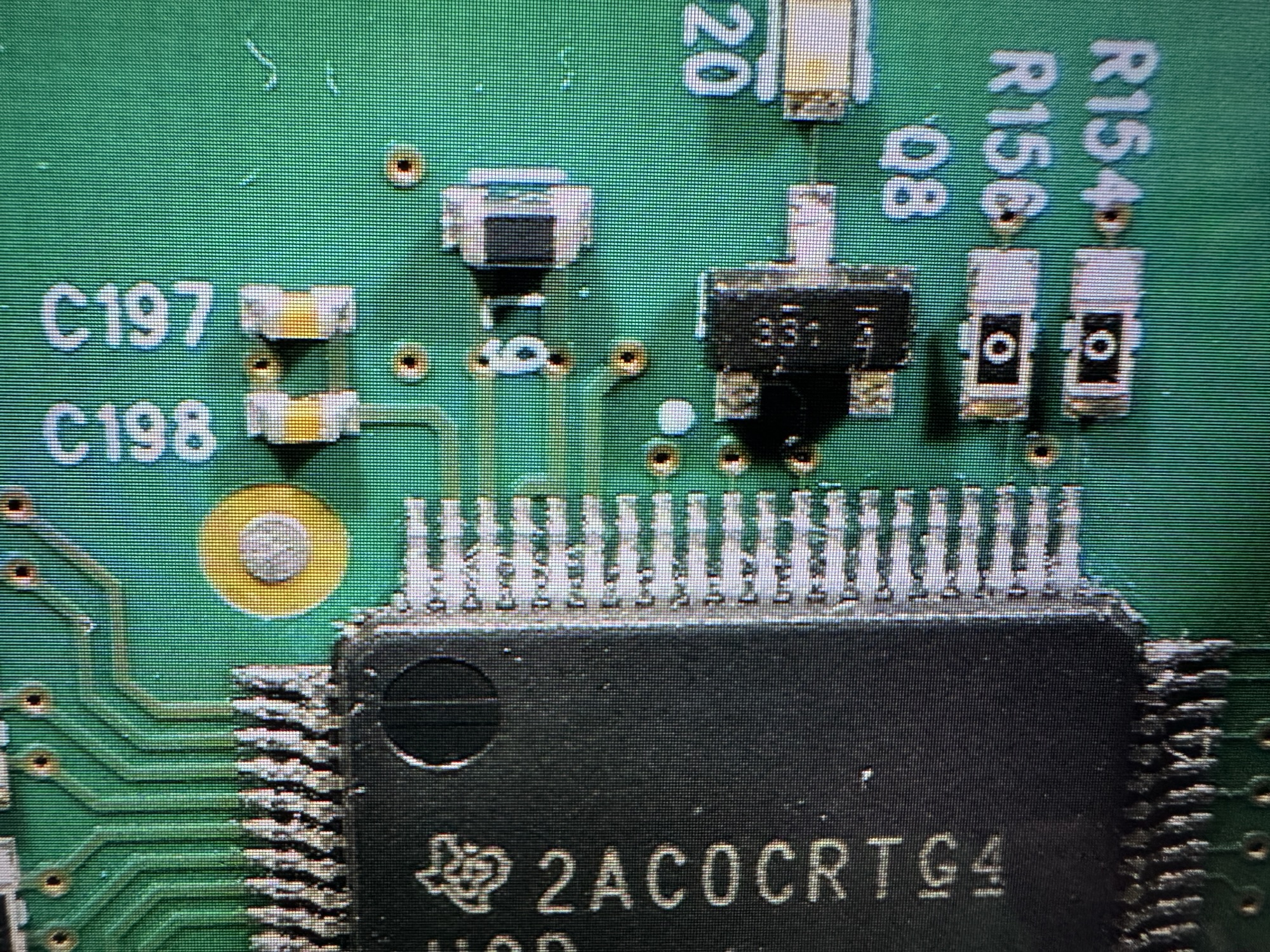
The finished swap
A chip that looks right under the microscope isn’t proven yet. At 0.5 mm pitch, a lead can sit on its pad without being soldered to it, and a bridge can hide under a lead where no camera angle reaches it. So once it was down, I verified all 80 pins three ways:
- Mechanical. I pushed on every lead with tweezers. A lead that’s actually soldered doesn’t move. One that’s only resting on its pad flexes.
- Connectivity. I measured resistance from each pin to the test point or component it routes to, confirming every joint actually connects pin to trace, not just lead to solder.
- Shorts. I checked continuity between every pair of adjacent pins, to catch a bridge too small or too well hidden to see. A few adjacent pairs did beep. I checked those against the UCD9248 datasheet, and they were ground pins that are supposed to be tied together.
Everything checked good, and the headers and passives around it came through untouched.

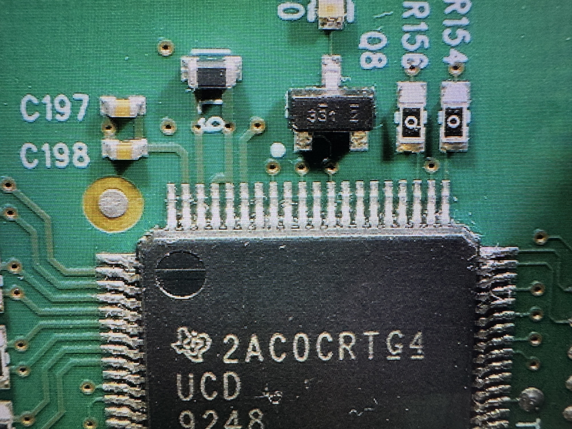
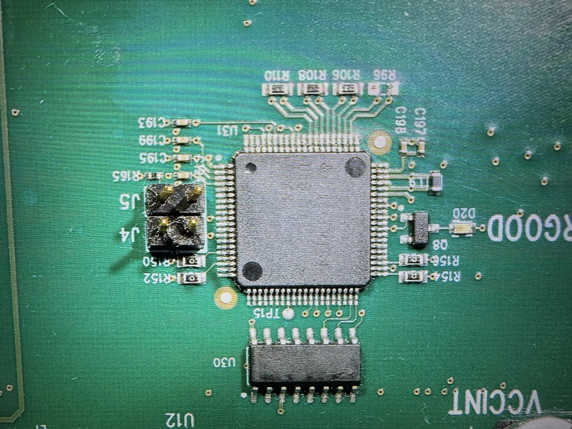
The takeaway
A fine-pitch, 80-pin power controller is not a part most shops will touch, and on a board like this the usual answer is to replace the whole board. With the right prep, it’s a component swap. Most of the work in a job like this happens before and after the hot air: protecting everything around the chip that can’t take the heat, then proving every one of the 80 joints is good before the board goes back.
Got a board with a failed controller, regulator or fine-pitch IC? Circuit Surgeon does board-level diagnosis and repair for customers in Oak Ridge and surrounding areas in East Tennessee, and by mail. Start a repair request or see how to ship your device.