
This board came in on its own, pulled out of a beer cooler. The complaint: power it up and the display blinks twice, then goes out and stays off. The cooler never starts cooling.

How this controller works
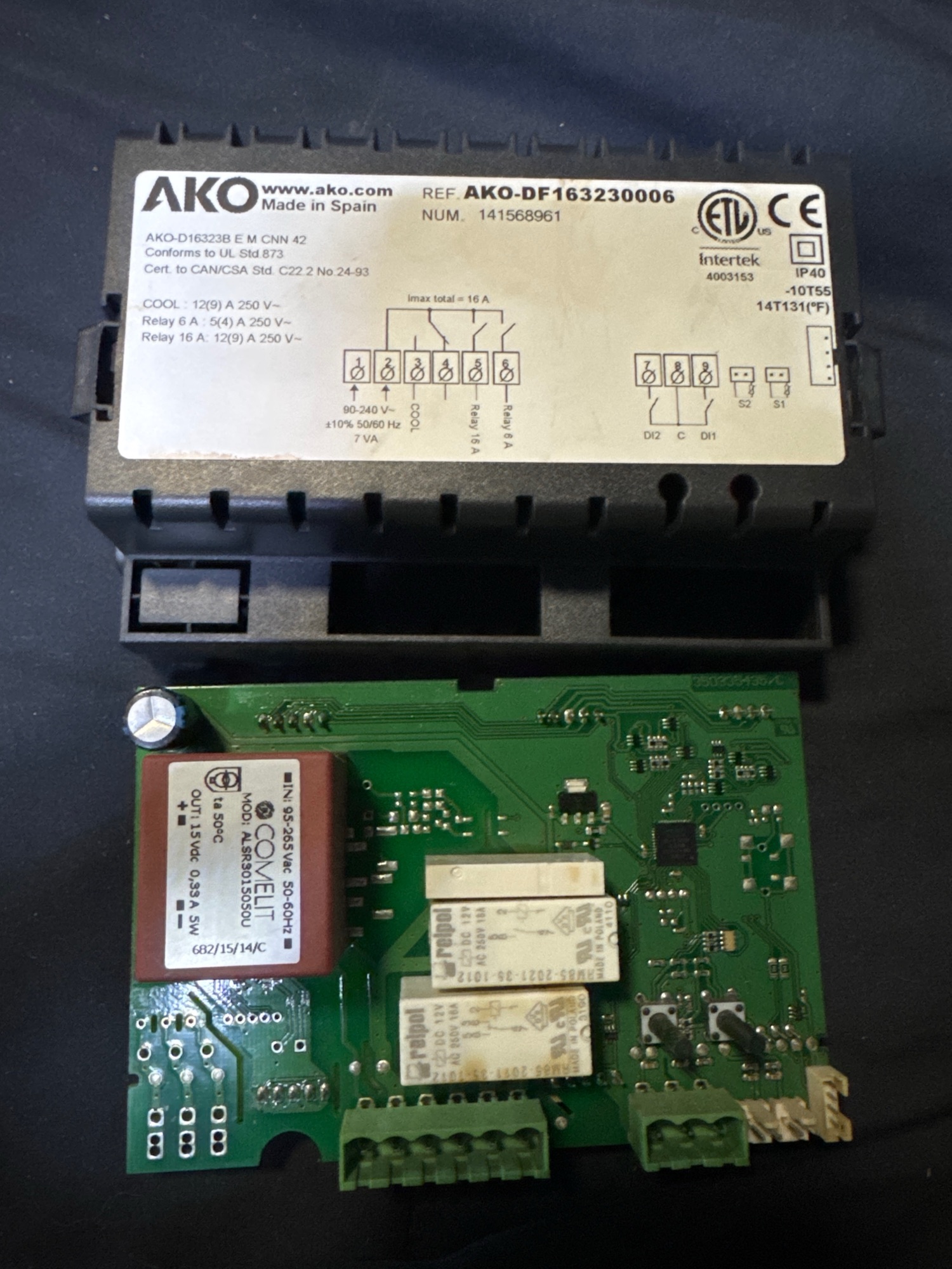
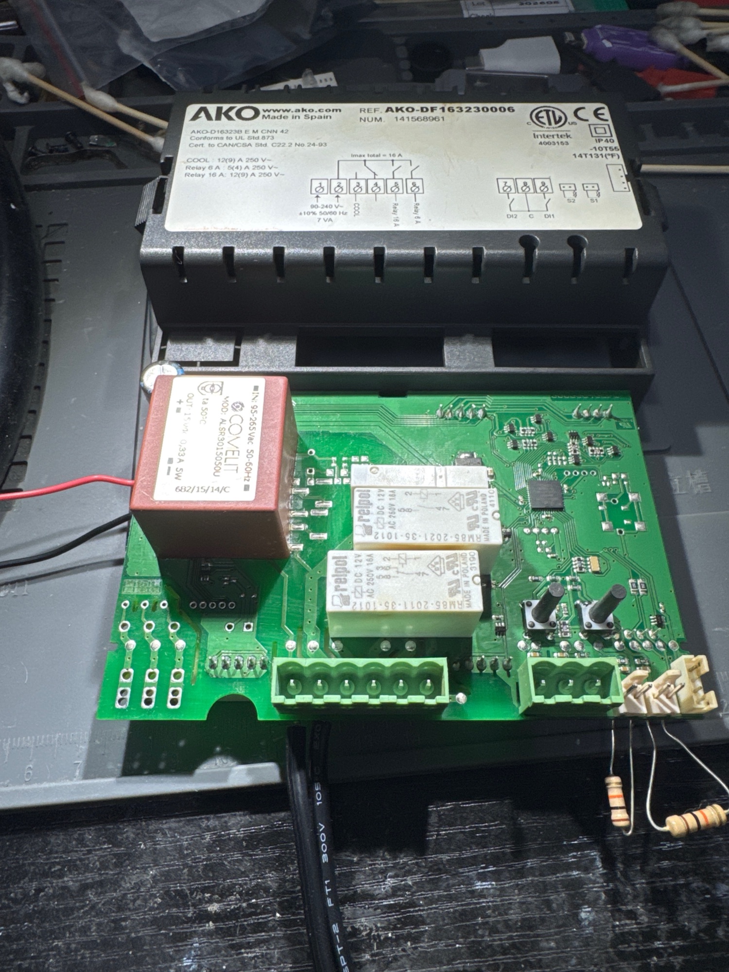
The board is an AKO refrigeration controller, marked AKO-163238. AKO is a Spanish maker of refrigeration controls, and boards like this run a lot of commercial coolers. Its brain is an Atmel (now Microchip) ATxmega32A4, a 44-pin XMEGA microcontroller.
What it does is simple. Two temperature probes plug into the S1 and S2 inputs. Each probe is a thermistor, a resistor whose value changes with temperature. These are 10k NTC types, meaning they read 10 kΩ at about 25 °C and drop in resistance as they warm up. The microcontroller runs a loop: read the probe resistance, convert it to a temperature, show it on the display, and switch the compressor relay on when the temperature climbs past the set point. A separate red switch-mode power supply (SMPS) module turns the 115 VAC line into the 15 VDC the board runs on.
First suspect: the capacitor
My first step on any board is going over the whole thing: inspecting and touching up solder joints while I look over the chips and circuit layout, to get a lay of the land and narrow down which sections need a closer look.
A board that powers up for a moment and then dies usually points at power, and the first part I suspected was the 470 µF 35 V electrolytic filtering the 15 VDC rail. A filter cap that’s lost capacitance or gone high-ESR can let the supply sag the moment the board draws current, and the micro browns out and quits. So I pulled it to test it off the board.
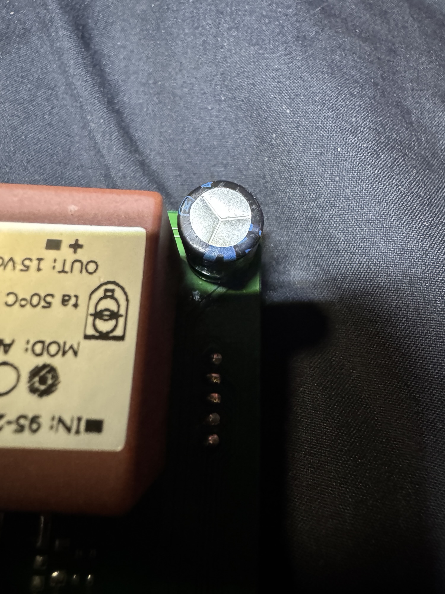

It tested fine: correct capacitance and low ESR. It’s a Jamicon, a decent brand, not a no-name part prone to failing early. A good cap gets reinstalled, not replaced just because it was the usual suspect, so it went back on the board.
The real fault: corrosion on the microcontroller
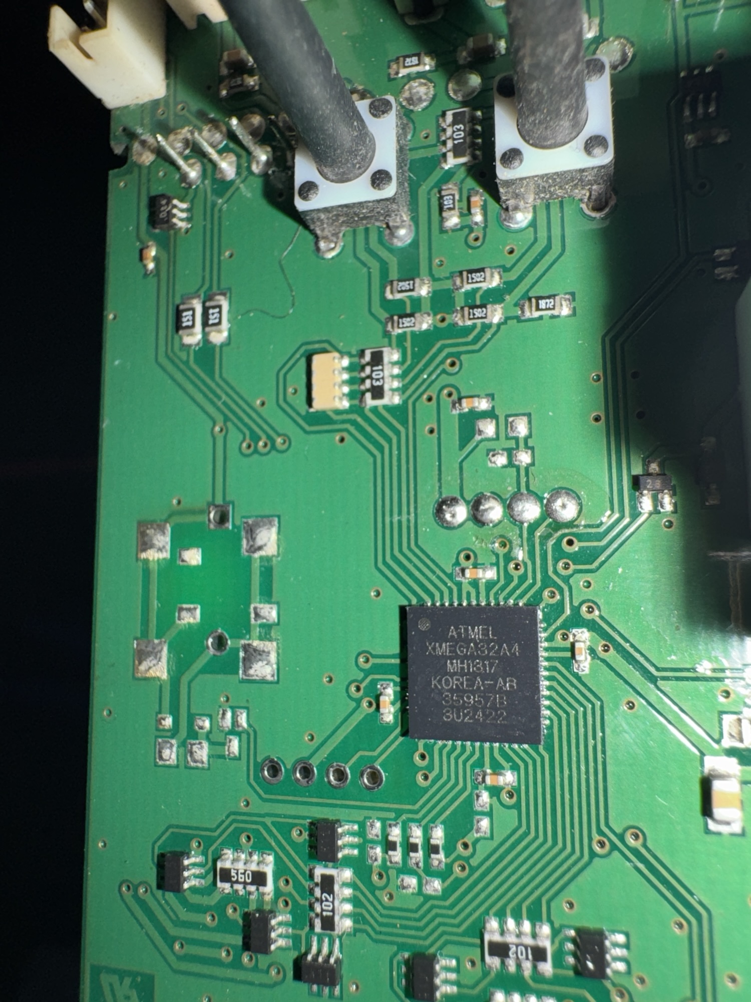
Under the microscope, I found a small spot of liquid corrosion on the pins of the XMEGA chip. Coolers live with condensation, and a little moisture finding its way onto a fine-pitch chip is enough to cause trouble: corrosion can leave a pin with a weak connection, or leak current between neighboring pins that should be isolated. A microcontroller with marginal pins can start, run for a moment, and fall over, which is exactly what this board was doing.
I went over the chip’s connections with flux and an iron to reflow every joint through the corrosion, then cleaned the area with isopropyl alcohol. Between that and the solder touch-ups across the rest of the board, the fault came down to two things: the corrosion on the microcontroller and weak solder connections.
Getting power to the board on the bench
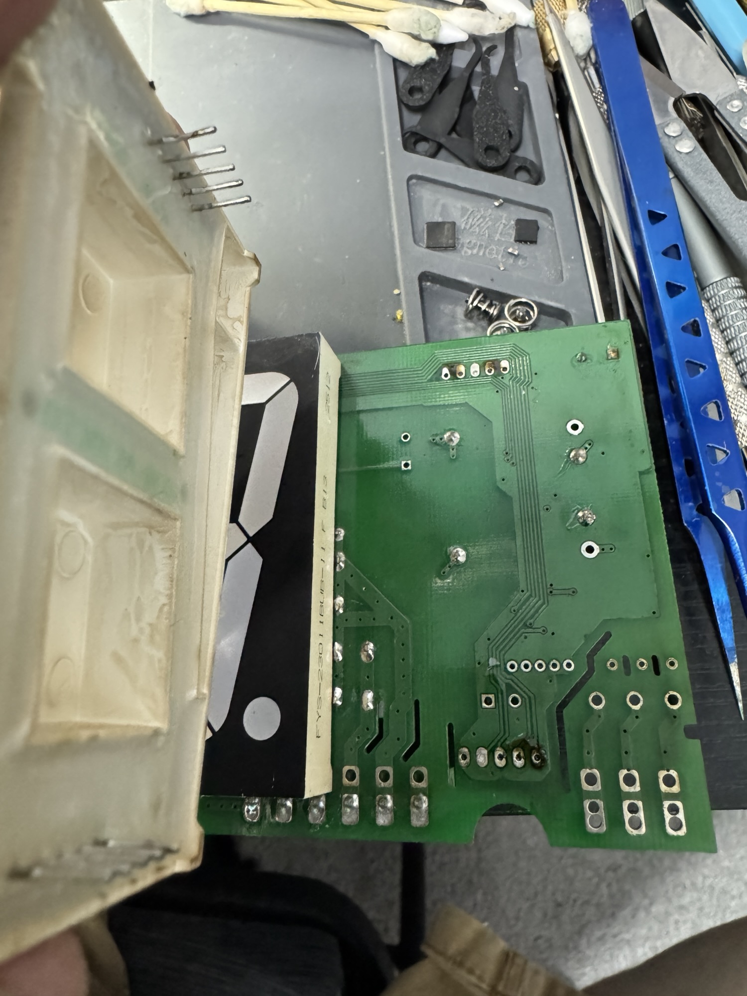
To test the board without its supply module, I needed to feed it 15 VDC directly, and the spot to do that was underneath one of the seven-segment displays. I removed that display, soldered wires to the + and − points, routed the wires underneath where the display sits, and soldered the display back in place over them.



Faking the temperature probes
With only the board on the bench, there were no probes plugged into S1 and S2. The controller sees an open input as a failed sensor, and it said so: it flashed an error sequence with E1 and E2, one code for each probe input.
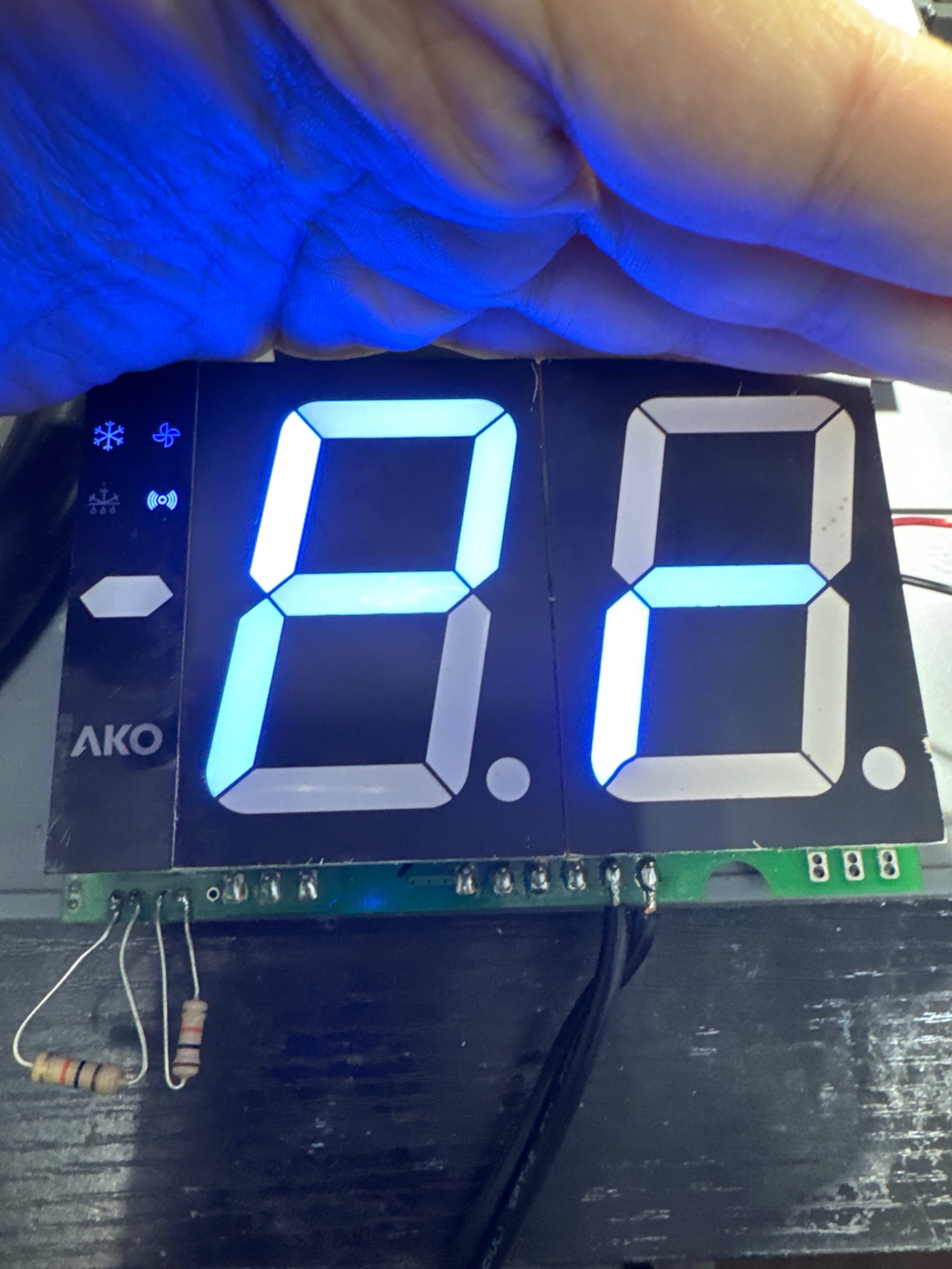
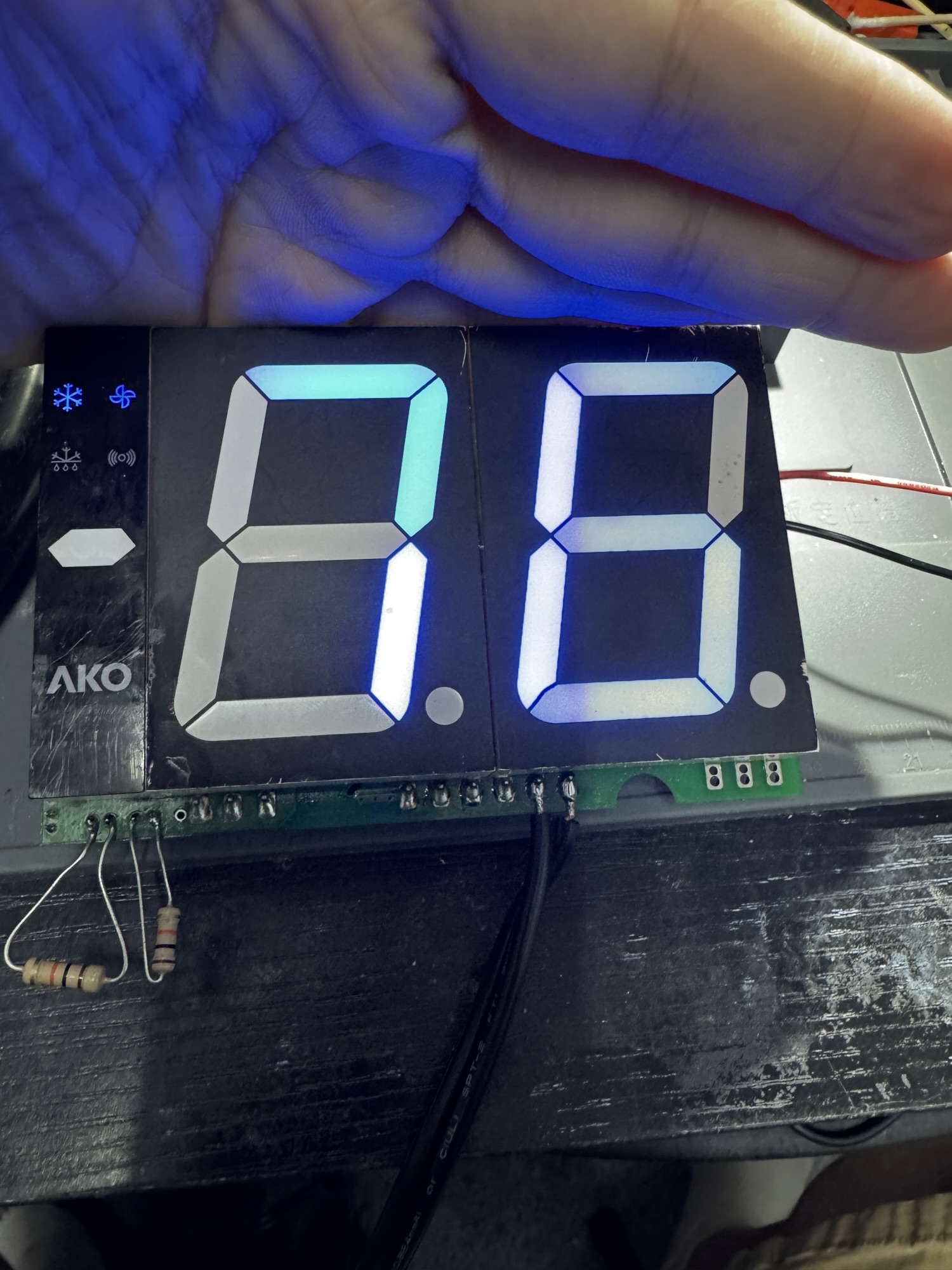
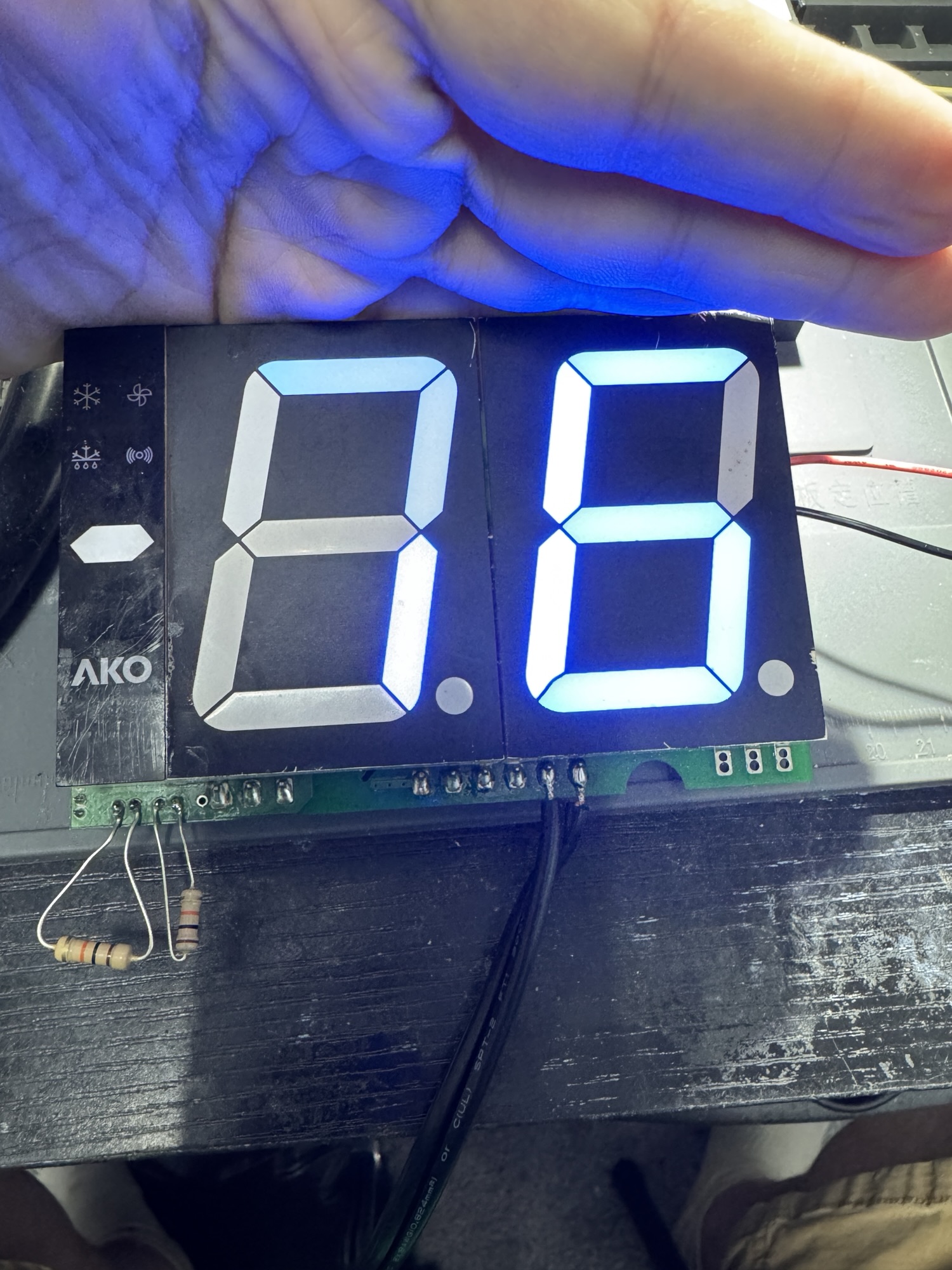
Since a 10k NTC thermistor reads 10 kΩ at about room temperature, a plain 10 kΩ resistor across each input looks to the controller like a probe sitting in a 25 °C room. With 10k resistors on S1 and S2, the errors cleared and the display showed a temperature. Changing the resistance changed the reading, and pushing it to the “warm” side made the controller switch the compressor relay. Input, logic, display and output all worked the way they should.
Protecting it from the next drip
A board that failed from moisture once will see moisture again, because it’s going back into a cooler. So after cleaning, I covered it with a layer of conformal coating, the thin, clear protective film used on boards that live around moisture. It seals the joints and pins against condensation so the same corrosion can’t start again.
Testing the 115 VAC supply module
The last piece was the red SMPS module that powers the board from the wall. To test it, I soldered an AC lamp cord to its input and brought it up on my variac through a dim-bulb tester. The variac raises the line voltage gradually instead of hitting the supply with full voltage all at once, and the bulb in series limits the current, so if something in the supply were shorted, the bulb would light up and take the hit instead of the supply. At 115 VAC it put out a clean 15 V. I left it running overnight to make sure nothing drifted or failed once it warmed up, and it held.
The takeaway
Refrigeration controllers live in a wet environment, and a little condensation on the wrong chip is enough to take one out. The obvious suspect here, the capacitor, turned out to be fine. Testing it instead of swapping it is what kept the search going until the microscope found the real problem. A replacement controller board costs far more than cleaning, reworking and coating the one you have. Faking the probes with resistors and testing the supply on its own means the whole board is proven on the bench before it goes back in the cooler.
Cooler, fridge or appliance controller acting up? Circuit Surgeon does board-level diagnosis and repair for customers in Oak Ridge and surrounding areas in East Tennessee, and by mail. Start a repair request or see how to ship your device.