
This Ubiquiti AmpliFi Alien came in with a problem a lot of owners have posted about and nobody seems to have solved: the 2.4 GHz band stopped working one day, all at once. The 5 GHz side kept going, but 2.4 GHz was simply gone. The owner had already done everything right on the software side. He changed settings, reset and reflashed the firmware, and Ubiquiti support even reviewed his NVRAM settings. Support’s conclusion was that the Qualcomm radio chip had failed.
It hadn’t. The actual fault was a single ceramic capacitor about the size of a grain of rice.
The usual advice for a router like this is to buy a new one. But the Alien is a strong router, it covers his entire house, and buying a used one off eBay would mean gambling on a unit with the same latent failure. So he looked for someone to repair it instead.
Why “it’s the chip” usually isn’t the first suspect
When one radio dies and everything else on the board keeps working, it’s tempting to blame the radio itself. But a radio needs clean, steady supply rails to run, and those rails are made on the board by small switching regulators: a PWM controller, an inductor, and a bank of output capacitors. If one of those rails collapses, everything that depends on it stops, and from the outside it looks exactly like a dead chip. The firmware can be perfect and the settings can be perfect, and none of it matters if the hardware underneath isn’t getting power.
So before replacing anything expensive, the first job is to check the power.
Step 1: Inductor-to-ground on every regulator
Visual inspection under the microscope didn’t show anything obvious, so I went to measurements. With the board unpowered, I measured resistance from the inductor of each buck regulator to ground. Each rail has a characteristic reading, and on a healthy board none of them are near zero. Every rail looked normal except one, which read about 0.2 Ω. That’s a dead short.
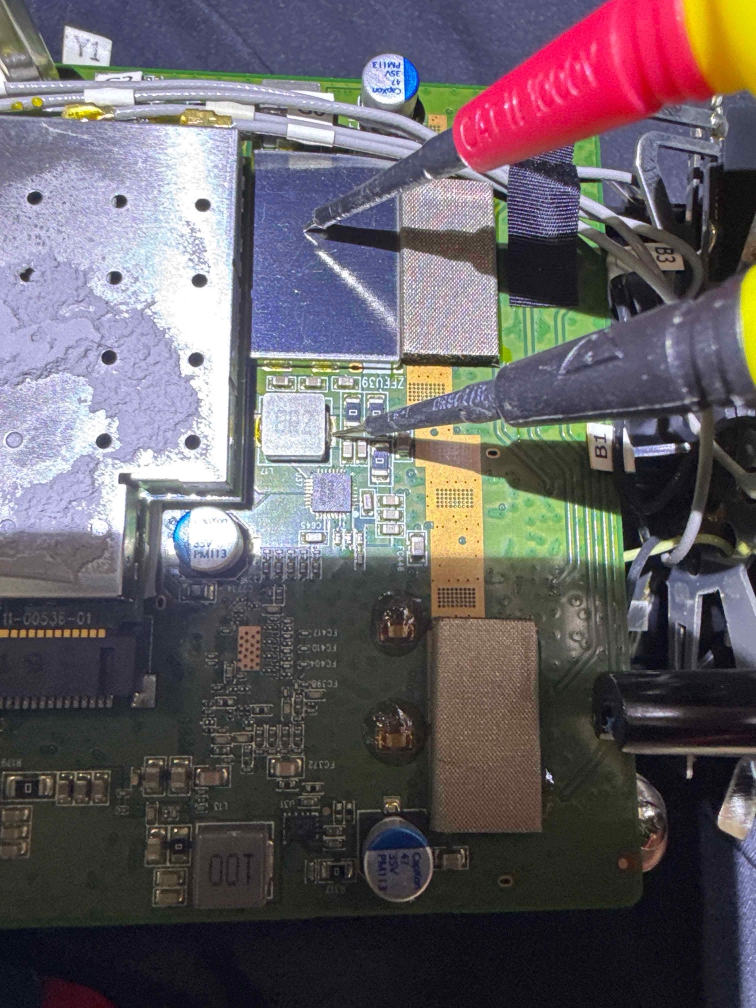

That regulator sat right next to the 5 GHz mini-PCIe card carrying the Qualcomm chip, so the first thing to rule out was the card. I pulled it. The short stayed, which cleared the card and kept the fault on the main board.
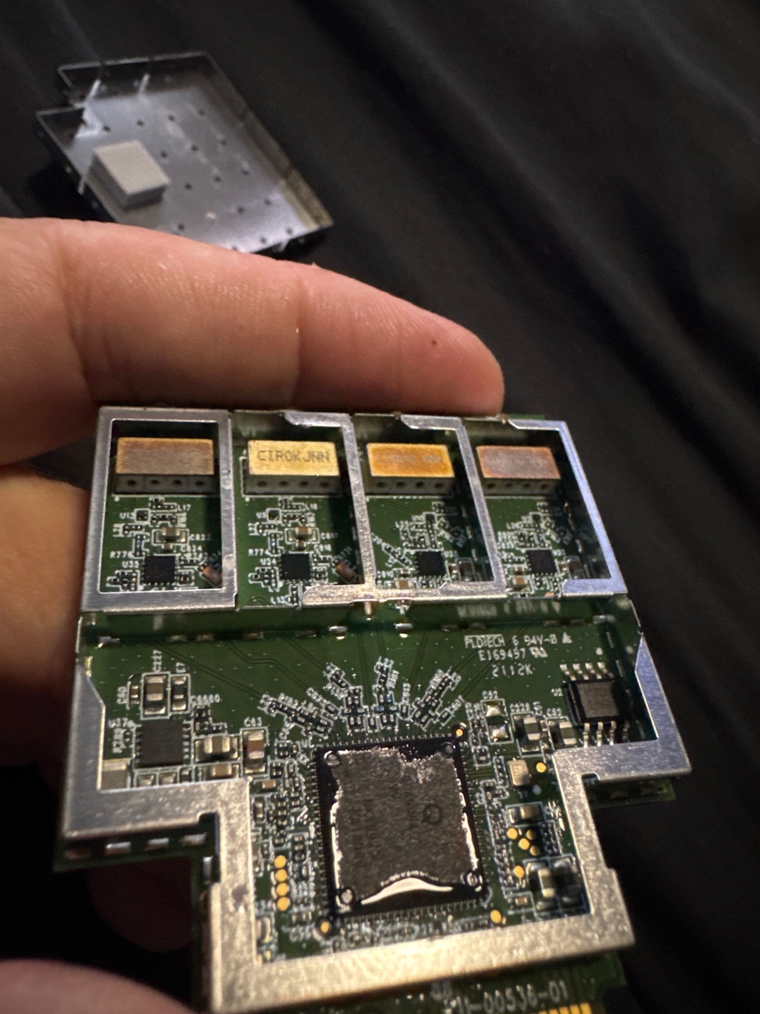
Step 2: Lift the inductor to see which side is shorted
The inductor in a buck converter sits between the switching stage and the output. Removing it splits the circuit in two, so you can tell whether the short is on the controller side or the output rail.

With the inductor off, one pad measured normal and the other still read about 0.3 Ω to ground. Now I knew which net the short was on.
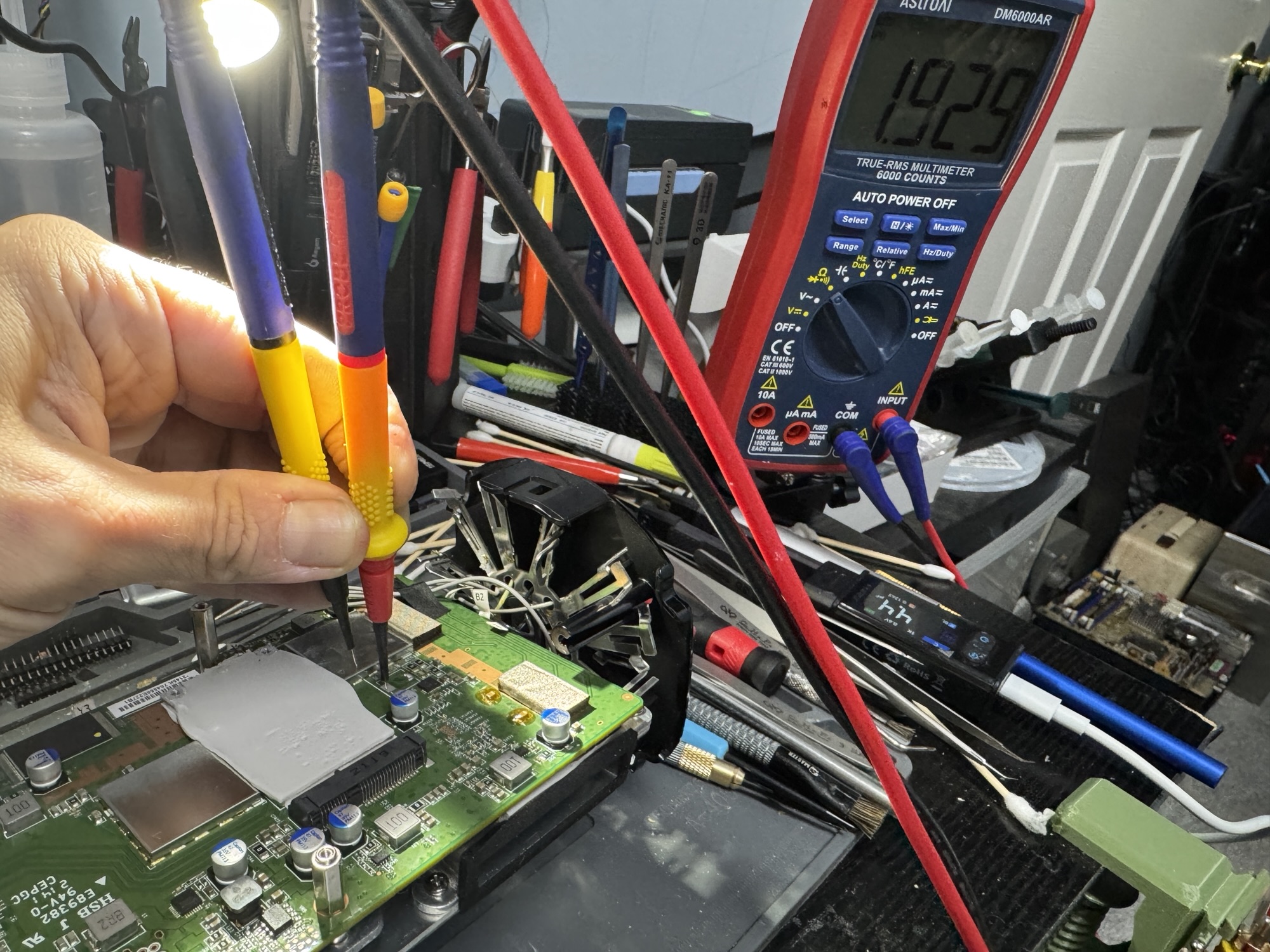
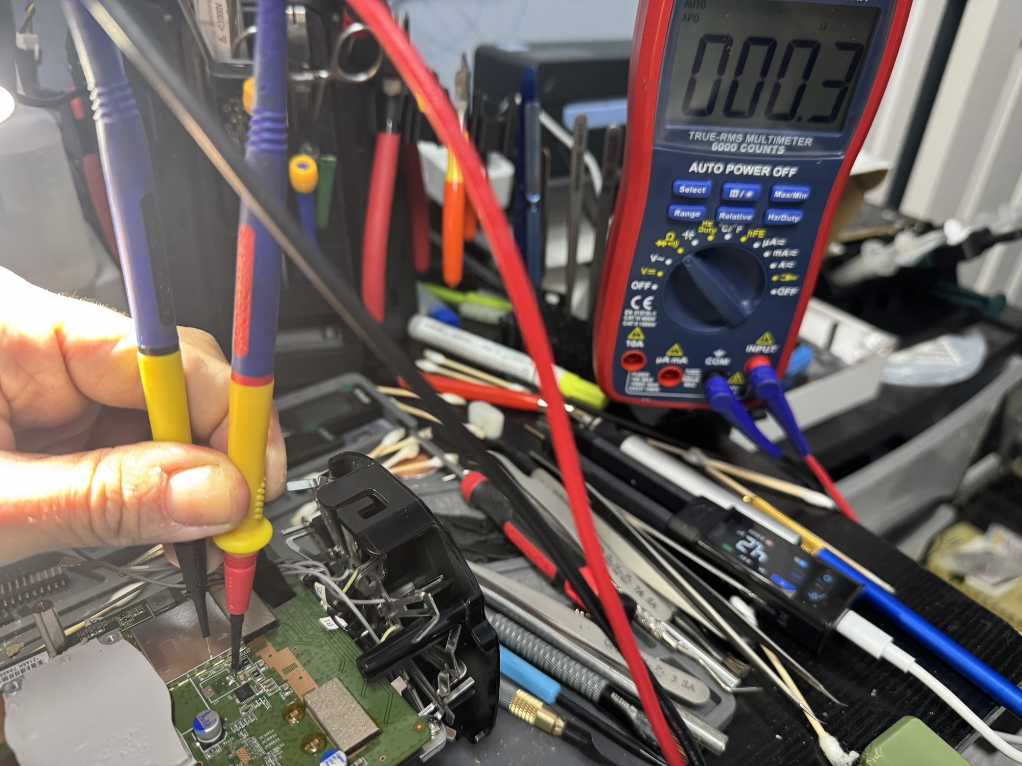
Step 3: Voltage injection and a thermal camera
A shorted net can connect to dozens of components, and a meter can’t tell you which one is the culprit, since they all read the same 0.3 Ω. So instead of measuring, I made the short reveal itself. I soldered a lead to the shorted pad and another to ground, and fed the net from a bench supply at about 1 V with the current limit set to 1.5 A.


Keeping the voltage low matters. At around 1 V, healthy silicon on the rail mostly stays off, so nearly all the current goes through the short. Whatever is shorted turns that current into heat, and a thermal camera shows exactly where.
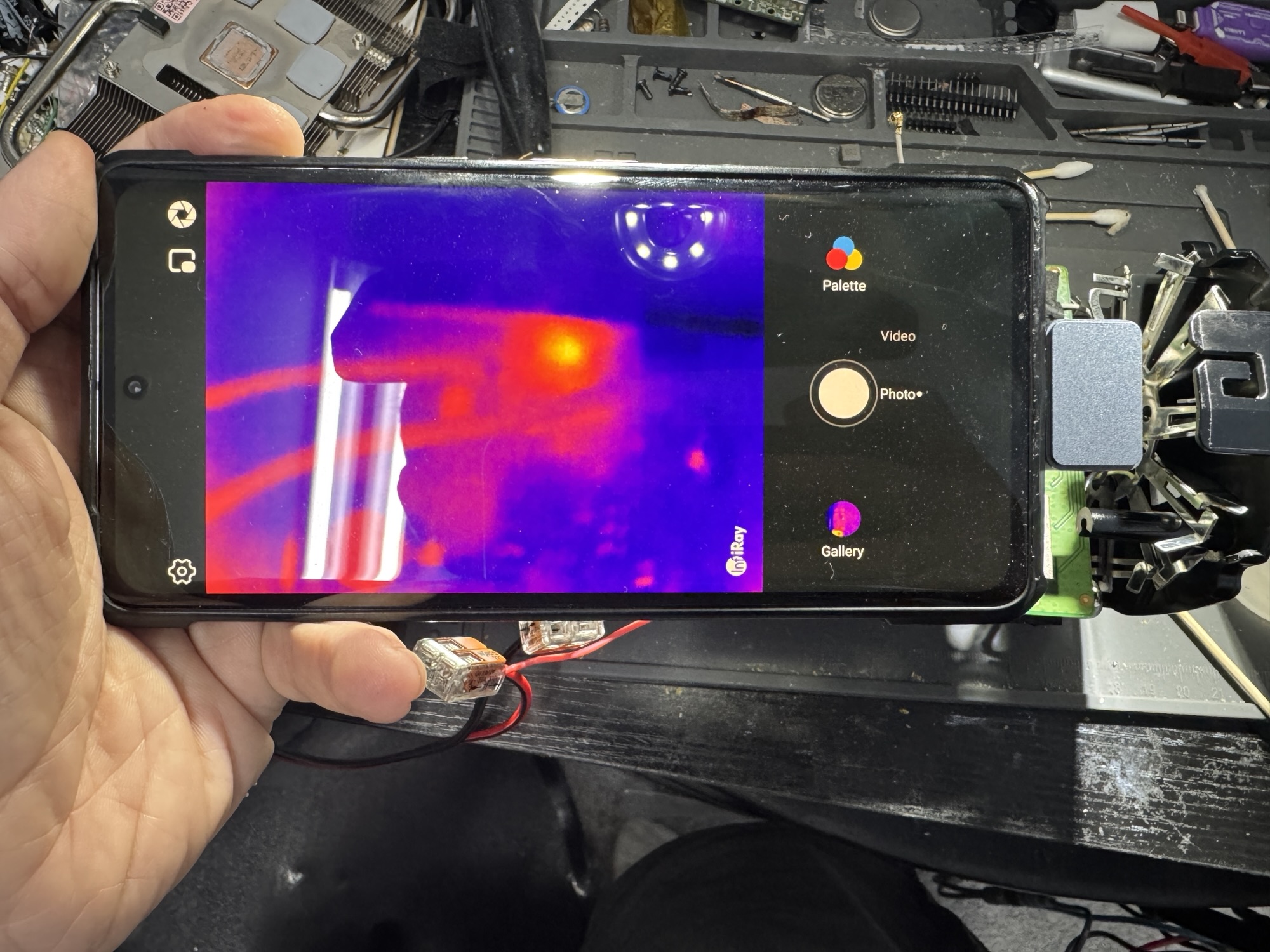
The hot spot was very close to the inductor footprint, in a small cluster of ceramic capacitors. To narrow it down to a single part, I applied a little isopropyl alcohol over the area. Alcohol evaporates fastest off whatever is hottest, so the shorted component is the one that dries first. That pointed to one 0805 ceramic capacitor, and under the microscope it had a visible crack across its body.

Step 4: Figuring out what the capacitor should be
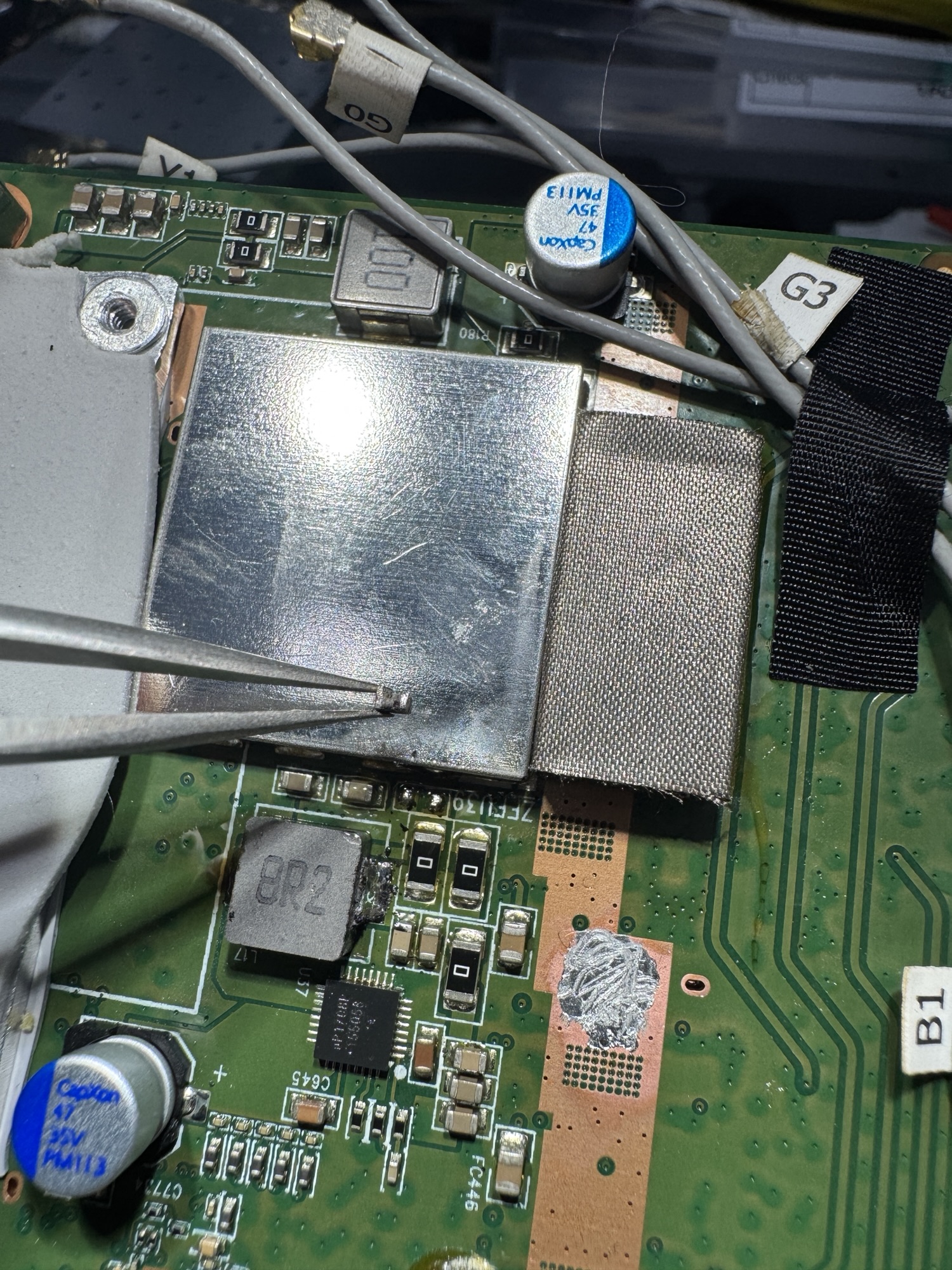
Ceramic capacitors have no markings, and a shorted one can’t be measured. To get the value, I removed a neighboring capacitor from the same bank and measured it with LCR tweezers, then checked the datasheet for the nearby PWM controller to confirm what output capacitance that regulator expects. Both pointed to 22 µF in an 0805 package.
With the shorted capacitor removed, the rail went from 0.3 Ω to 17.22 kΩ. That confirmed it was the only failed part on that net.


Step 5: Replace all three, with more margin
There were three 22 µF capacitors in that bank. The two that hadn’t failed measured 17.6 µF and 18.6 µF. For a 22 µF part with a typical ±20% tolerance, 17.6 µF is right at the lower limit. That’s low in my experience for capacitors in this position. They had the same age, the same thermal history, and came from the same batch as the one that cracked, so I replaced all three.
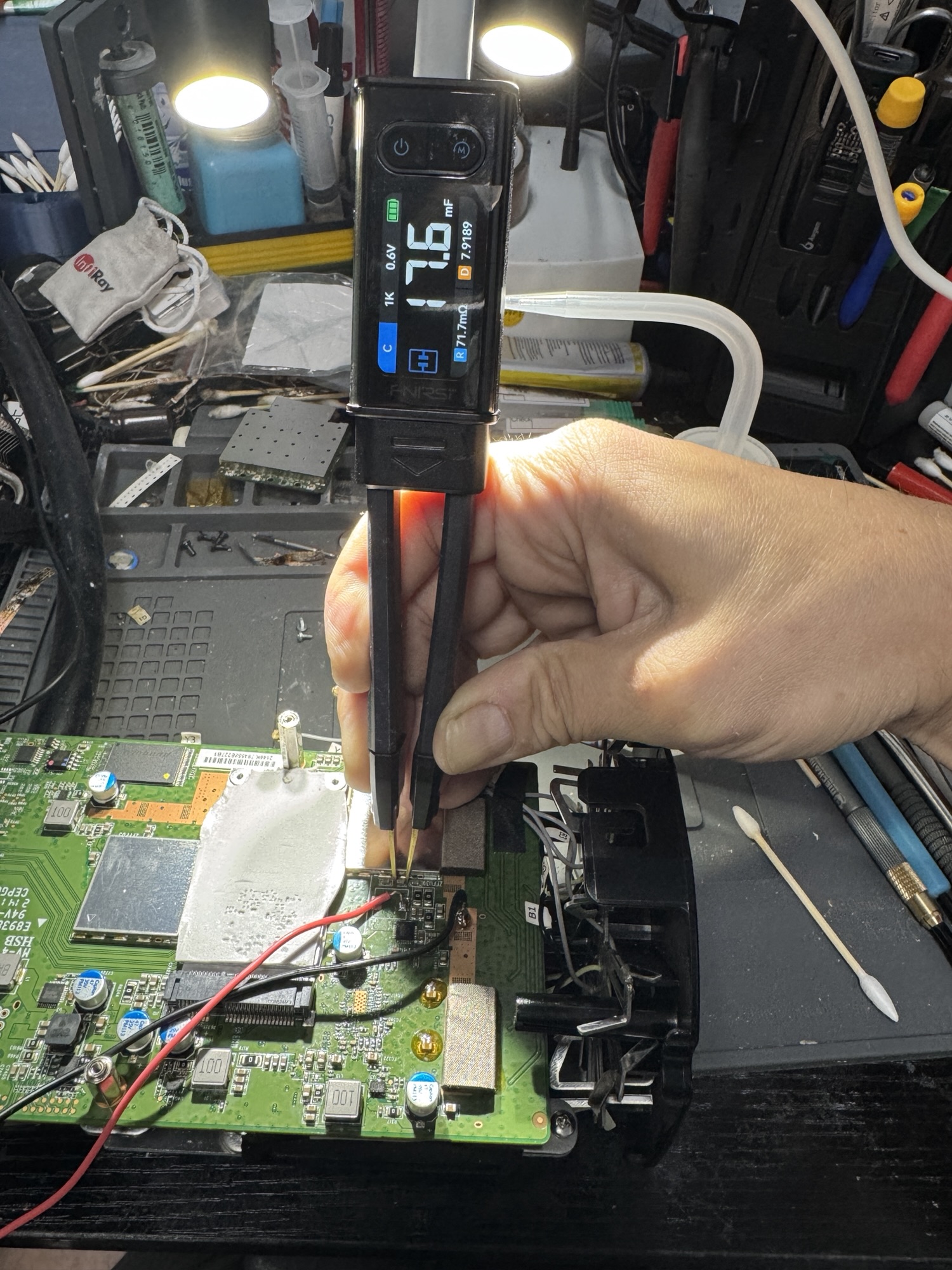

For the replacements I used 16 V-rated X5R parts. A high-capacitance ceramic in a small package like 0805 is a stressed component. It loses a lot of its effective capacitance under DC bias, and the parts with the lowest voltage ratings lose the most. A higher voltage rating in the same package gives more margin on the same rail. It won’t make a capacitor immune to cracking, but it’s a better part for the job than the original.
Why ceramic capacitors fail short
Multilayer ceramic capacitors (MLCCs) are built from many thin ceramic layers stacked between metal electrodes. When the body cracks, from board flex, or from repeated heating and cooling inside an enclosure that runs warm all day, the crack can bridge electrodes of opposite polarity. Often the capacitor works for a long time and then fails suddenly as a short. That matches what owners describe with this router: it worked fine, then 2.4 GHz disappeared overnight with no warning. It also explains why no settings change, reset, or firmware version could ever have fixed it.
Testing it afterward
With the inductor reinstalled and the router reassembled, the 2.4 GHz band came back and has stayed up. Beyond basic speed tests, I ran iperf3 between two laptops on the router’s 2.4 GHz network for long stretches, in one direction, in reverse mode, and in bidirectional mode, to make sure both directions held up under continuous load.


One continuous reverse-mode run went about 16 minutes, moved 2.18 GB, and averaged 19.5 Mbit/s with very few retransmissions. Bidirectional runs held about 15 Mbit/s up and 11 Mbit/s down at the same time. Both test machines were wireless clients on the same 2.4 GHz radio, so every packet crossed the air twice, once into the router and once back out. That roughly halves what any single client would see. The point of the test wasn’t peak speed. It was to confirm the radio stays up and the throughput stays steady for hours, and it did. The router is running an overnight soak test before it goes home.
The takeaway
If your AmpliFi Alien’s 2.4 GHz band suddenly died and nothing on the software side brings it back, the radio may not be the problem. A shorted capacitor on a supply rail produces exactly the same symptom. That’s a repair measured in a few cents of parts and some careful bench work, not a new router.
Router or network gear with a dead band or no power? Circuit Surgeon does board-level diagnosis and repair for customers in Oak Ridge and surrounding areas in East Tennessee, and by mail. Start a repair request or see how to ship your device.